Having reached the point of getting the major components to turn, the next step is to strip the engine down, and complete the block, and then paint, before erecting the entire assembly and tackling the valve gear. Continue reading
Tag Archives: cylinder
Porting
Some jobs just feel like they should be done later… In this case it was cutting the ports in the cylinders and valve chests – you have spent so long getting a nice accurate bore, and now you are about to cut holes in it! The scope for disaster is all there – it reminds me of being given the job of fitting car aerials to new Audi’s as an apprentice in the ’70s – somehow attacking a brand new top-of-the-range motor with a power drill was just a very scary process!
So firstly I marked out the ports on the mating faces of the castings, on a surface block to provide a check when machining (the old addage – “measure twice, cut once”) then converted all the dimensions from the drawing into coordinate dimensions from the centreline base of the cylinder, as I had decided to use the mill’s DRO in “jig boring mode”.
I can’t tell you how many times I checked these dimensions, as on the drawings they are marked from top and bottom, but we needed them all as offsets. ….and it payed off, I found a mistake or two!
The next step was to start machining, I fixed one angleplate to the mill table (accuratly across it) and then set the DRO zero here, then mounted each of the castings between this and another angle plate and set to with the slot drills – tense moments!

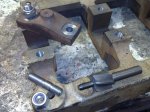
milling the ports in the LP cylinderLP cylinder and valve chest ports in place!LP cylinder ports with lower cover in place
Boring Bar Blues
It seems I am getting lax at downloading the pictures from the new Nokia N8 to update the blog, so here is a quick summary of the progress being made.
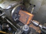
I have a couple of pictures here of boring the high-pressure cylinder and piston-valve chest – the problem with these two is that they are too small and long to allow me to get the boring head in – and I have an inbuilt hatred of between centre boring bars – so thy had to be bored with a long boring tool… (here’s a video) This is right at the start of the boring process, and the cored hole in the casting is somewhat off centre, so at this point it all looks a bit wobbly and we have an interrupted cut in progress.
This approach to machining has resulted in the bores being a bit tapered [wear in the 60-year-old Harrison’s bed 😦 ]. It looks like they might be about 2-thou off parallel, so I will need to pay some attention to this. For the piston valve I can probably make the liner match – for the cylinder perhaps some AGGRESSIVE honing might help… we’ll see.
Screwing away
Decided to fit the main bearing caps, these are meant to be fitted with 7/16 Whit studs and nuts, but with a nod to modernity we broke the mould and went for UNC!!!
It transpired the threading 7/16 rod with a tailstock die-holder was ambitious (even after I had to make the aforementioned die holder), so we set about screw cutting a set of studs and using the die as a chaser – a nice simple job…
The “scrap-bin” produced an old and blunt counter-boring tool – but the Quorn fixed that and produced a nice job.
The pilot holes for the caps had been drilled in France, so I hoped this was accurate and followed them, and wound up with an almost perfect fit.
Finished the day by jig-boring the cylinder base mounting jig (angle plate with dummy piston rods clamped to the slideways.. and took a first skim over the top of the HP cylinder – although for some reason the facemill started chattering….
A nice weekend’s work….
A week’s good work (part 2)
 This seemed like a major milestone – starting work on the Cylinders….
Decided to do the LP one first – the game plan is to rough skim the top (to provide a footing to rest it on when turned over) then machine the base and bore in one go thereby ensuring that the piston rod in the bottom cover and the piston in the bore are truly in line…
So, as planned we mount the casting square on 1-2-3 blocks to provide clearance to bore thru, and use 80mm facemill (a freebie from somewhere with new tips and arbours from Greenway Tools (a very good firm))…
quelle dommage – cracks!
The first cut over the casting throws up a major worry – not one, but two cracks in the casting, one of which clearly runs from top to bottom 😦
Given that I purchased them second-hand, there is no chance
of a replacement, so I figure they might just machine out.. and set off boring the casting – having first made a bush with a carefully miss-aligned hole so I could use a straight HSS tool bit in the boring head.
While the first couple of cuts just panicked me even more – the crack looked huge, I just kept going and it all came out beautifully – with a LOT of swarf!
A very nice result – and I breathed a sigh of relief as there were a set of Leak castings on show at the exhibition, and the builder had clearly had some problems with the bore, as the finish looked very iffy….
Followed this up with machining the LP valve chest (a bit tricky to get into the corners of the inner valveface, but all came out OK…
A week’s good work
I took most of the half term week off and with the weekends before and since real progress is being made.
I am also learning how to make sense of the notes from Mr. Leak, and decided to buy an up-to-date set of plans from Camden… this is all leading towards making progress…
Rear Columns
Firstly to return to the columns – as noted earlier I machined these individually on the milling machine, but eventually concluded that they were not “perfect”. The two columns were about 8-thou different in hight, the tops were not completely orthogonal (about 4thou front to back) and the milling cutter was not completely true, so there were ridges. (here was this intial set up)
I spend a day “getting things true” – resetting the vertical head on the mill to within about 2thou over a 6 inch distance (front to back) and to a similar accuracy over a 10 inch distance left to right. I spent half a day trying to resharpen the flutes on the milling cutters on the Quorn to the desired degree of accuracy, and failed (marked down roller-bearing or air-bearing tool holder as a future necessity – just too much stiction/slop in the current arrangement to do good work). (I will re-create this set up and take a picture later!).
The backs of the columns (air pump slideways etc.) were also finished on the shaper – right at the capacity limit of the wartime, American, lend-lease machine – but as always it produces a really nice finish with simple tools and is quite relaxing to watch too!
In the end the columns were returned to the miller to have the rest of the “rear” surfaces finished with a flycytter and long-series end mills…
In the spirit of “getting it right” I purchased a new angle plate at the Midlands model engineering show, and then learnt and practised the craft of hand scraping with engineer’s blue to get it flat etc.
Then fitted this angle plate to the side of the shaper (to make a “lower table”) and managed to get the two columns fitted (side by side) onto that with the slideways clamped to the side of the table, and then was able to re-finish the tops of the column. A much more satisfactory finish – no discernible difference in height between the two (phew!)
 the column erection jig in place
You can see them “tested” against the erection jig (adjusted for the over-width main bearings here…
Cylinder Bases
 Then I started on the cylinder bases. A nice return to lathe work! A simple job, first facing off the inside faces, and drilling/boring/reaming the 3/4″ hole for the piston rod, then clamp it face down on the milling table and face the mounting face, and bore for the gland/stuffing box.

drilling the pilot hole for piston rod in LP cylinder bottom cover fly-cutting the mounting flange on the HP cover
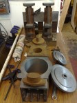
Soon a pair of nicely finished covers emerged – now the fun begins…. getting to grip with the cylinders…


