Tag Archives: milling

Steamboat Crankshafts – Lessons & Manufacture Pt#2

This post continues/concludes the story of manufacturing a new crank for Befur from the last post.

Here we can see the re-assembled engine with new crank. We are still to install all the ancillaries (reversing gear, lubrication, condenser and feed/air pump & alternator drive.)

It took 6-man days from receiving the crank back from the grinders to reach this stage.

Once we have tested it on air, we will reinstall it on the boat and undertake this year’s boiler test and check all is as it should be.

Machining Crank Pins

Continue reading

Relief Vales and Drain Cocks

An experiment – Steam Operated Combined Drains & Relief

Much earlier in the process I baulked at drilling the cylinder castings for the cylinder drain cocks because they looked hard to drill with out risking damage to some rather expensive castings. Moreover, previous experience with manual cylinder drain cocks on the loco had been poor (leaky, difficult linkages etc.) and on the steam launch most people seem to opt for 4 manually operated cocks which involves a deal of “faffing” in use. Continue reading

A bit of an upgrade

Malcolm’s a happy boy!

Much as I love the Adcock and Shipley milling machine that Andy Murdock found for me in a Car Park in Runcorn in the early 80’s, and despite the sterling service it has provided with the Bridgeport head I fitted, I had yearned after a machine with a bit more capacity for a long time, and with the “pending boiler” build, I decided the time had come to find its replacement….

I had intended to buy a Bridgeport “series 1” mill – and a bit of research demonstrated that you could buy “a bit of a nail” for about £1500, a passable example for £2500, a nice refurbished one for £7,500 or a new one for about £15,000!

After a lot of searching, and trawling ebay and looking at the cost of transport, I bit the bullet – sold the old mill on Ebay and went (with supporting friend) to look at few replacement machines … including at a dealer (BW Machines) in Leicester….

Well as with all “best laid plans” on arrival I did not much like the one I went to see, did not have enough funds to buy the ones I fancied, but fell across a ’72 Italian turret mill by Rambaudi… It took a while to convince myself I could move and install the thing (1.5tonnes), but it was in good condition and was obviously a very high quality machine, so the deal was struck…

So here’s a two pics of it arriving and of it almost in place – now I just need to fit a DRO, swap all my tooling to 40INT and resume work (currently on the auxiliary drive assembly for pumps and alternator) – it is BIG!

A hasty snap of delivery in progress

A hasty snap of delivery in progress

Rambaudi V3 in situ

Rambaudi V3 in situ

Chucking out the Chucks?

I realised the other day that I have almost stopped using chucks and vices. When I first got the milling machine (20+ years ago) I spent a lot of time looking for and building milling vices, and similarly on the lathe kept looking for nicer/larger chucks.

But in the last few years nearly all the milling/shaping is done by clamping work pieces directly to the table (either using clamps or stop-pins) , and when you do this you tend to wind up with more solid set-ups, with fewer errors from things slipping, and much more accuracy, and you are not plagued by lifting jaws putting things out of true etc.

Similarly on the lathe I seem to be doing more between-centres work, which I used to view as old fashioned, but I now realise it tends to be more accurate, and you can take a job off the lathe and put it back, and its in the same place!!!

That and the purchase of the ER25 collects and chuck have almost made use of the 3 and 4 jaw chucks a rarity.

I guess if I had had a proper apprenticeship or teachers watching, I would have learnt all this earlier – but none-the-less I am enjoying my improved productivity and accuracy as a result of this change.

Connecting Rods & Big Ends

The connection rods were a nice between-centers turning job, and then a selection of milling set ups.

Rather than write a lot, I will put some pictures below – the main thing to note was that almost all of the milling and boring was done with the partially machined big-ends attached to the partially complete rod – in order to ensure a good level of concentricity….

Nice New Main Bearings

As discussed in the last post, I decided to remake the bearings as drawn/described from  a solid Phosphor Bronze (SAE 660 aka Gunmetal) block – being as how I had needed to remachine the crank journals after assembly, and the first set of fabricated bearings were a bit “naff”..

So the first job is to cut the block in two (longitudinally) clean these two pieces into neat cuboids, and then soft-solder them back together for machining.

This time I decided to machine the bores first, and then mill the seatings for the housing by measurement from the bores – in this way you would be able to “guarantee” that the resulting bores all lined up!

Much more success!

One of the problematic things was how to measure the distance from the bore to the outer facing – this would need ball-faced micrometer, not something I had. After some thought this idea occurred: by hot gluing a ball bearing to the anvil (and remembering to subtract the diameter of the ball from what I measured) everything would be fine – and it was!

Home made ball-headed micrometer (ball bearing hot glued to anvil)

So  by first machining the back face of the bearing housing, and the bottom of the bearing housing to the correct dimension from the bore we knew that things would line up. Then the forward face could be machined to be a snug fit in the housing.

Lastly the top surface was machined to ensure the bearing keeps would provide a little “crush” when tight.

I cut everything to allow for a little hand-finishing (to make sure there was no slop), and then unsolder the two halves, clean up and try them on the journals – they were too tight!

But this was “kind of what I had planned”, so then fitting the bearings in place, and a few hours with the engineer’s blue and hand scraping we wound up with a crank fitted and turning pretty freely. (this description skips over the machining of the ends of the housings to provide for the correct end float, which was a bit “trial and error” – but all came out OK.

A slide show of the process…

This slideshow requires JavaScript.

Machining the Air Pump Slideways

I thought I would record this as a video, to show the machines in action.

The machining is being done on my Adcock & Shipley 1AD horizontal mill, that I bought for a fiver back in the early ’80s. I have grafted a Bridgeport J-Type vertical milling head onto this, and fitted with a home-build DRO (Shumatec design) – and I am quite chuffed with the result…

Stop Pins: the vice-free approach to thin things!

LP ValveChest Cover - held down with Stop-Pins...

LP ValveChest Cover - held down with Stop-Pins...

One of the nice ideas I came across in an old Shaper book was a way of holding thin flat things down onto a shaper.

The problem with thin things is that you can’t hold them in a vice, as the jaws prevent you working to the edge, and also you have the problem of the moving jaw lifting as you tighen the vice, and the work piece lifting from the floor of the vice, and thus getting machined skewed.

Stop-pins and t-slot located jacking screws

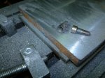
The idea with stop pins, is that you press small hardened pins into the side of the work with angled jack screws, these force the work flat onto the table. I have found by angling the pins, you can also locate the work laterally.

In this case I decided to use the same idea on the mill, to machine the LP valvechecst cover. On the Leak compound the LP valve is a balanced design which has steam-tight sliding valves on both the port-face and the valvechest cover (this reduces the net pressure on the valve face, and thus the stiction and driving forces) – but it requires the valvechest cover to be flat and parrallel to the portface. So ensuing the cover (and the valvechest proper) are held nice and flat when machining is vital – stop-pins to the ready!

A week’s good work

I took most of the half term week off and with the weekends before and since real progress is being made.

I am also learning how to make sense of the notes from Mr. Leak, and decided to buy an up-to-date set of plans from Camden… this is all leading towards making progress…

Rear Columns

Firstly to return to the columns – as noted earlier I machined these individually on the milling machine, but eventually concluded that they were not “perfect”. The two columns were about 8-thou different in hight, the tops were not completely orthogonal (about 4thou front to back) and the milling cutter was not completely true, so there were ridges. (here was this intial set up)

First attempt at finishing the columns on the verticle mill

First attempt at finishing the columns

I spend a day “getting things true” – resetting the vertical head on the mill to within about 2thou over a 6 inch distance (front to back) and to a similar accuracy over a 10 inch distance left to right. I spent half a day trying to resharpen the flutes on the milling cutters on the Quorn to the desired degree of accuracy, and failed (marked down roller-bearing or air-bearing tool holder as a future necessity – just too much stiction/slop in the current arrangement to do good work). (I will re-create this set up and take a picture later!).

Facing the airpump slideway mountings on the rear columns

easily done on the shaper – at the limit of the Ram’s throw!

The backs of the columns (air pump slideways etc.) were also finished on the shaper – right at the capacity limit of the wartime, American, lend-lease machine – but as always it produces a really nice finish with simple tools and is quite relaxing to watch too!

finishing the rest of the rear surfaces of the columns

finishing the rest of the rear surfaces of the columns

In the end the columns were returned to the miller to have the rest of the “rear” surfaces finished with a flycytter and long-series end mills…

In the spirit of “getting it right” I purchased a new angle plate at the Midlands model engineering show, and then learnt and practised the craft of hand scraping with engineer’s blue to get it flat etc.

Then fitted this angle plate to the side of the shaper (to make a “lower table”) and managed to get the two columns fitted (side by side) onto that with the slideways clamped to the side of the table, and then was able to re-finish the tops of the column. A much more satisfactory finish – no discernible difference in height between the two (phew!)

the column erection jig in placethe column erection jig in place

trying the rear columns agains the erection jig

trying the rear columns agains the erection jig

You can see them “tested” against the erection jig (adjusted for the over-width main bearings here…

Cylinder Bases

grabbing the bottom cylinder covers in the 4-jawThen I started on the cylinder bases. A nice return to lathe work! A simple job, first facing off the inside faces, and drilling/boring/reaming the 3/4″ hole for the piston rod, then clamp it face down on the milling table and face the mounting face, and bore for the gland/stuffing box.

drilling the pilot hole for piston rod in LP cylinder bottom cover

drilling the pilot hole for piston rod in LP cylinder bottom cover fly-cutting the mounting flange on the HP cover

flycutting the mounting flange on the HP cover

fly-cutting the mounting flange on the HP cover

Soon a pair of nicely finished covers emerged – now the fun begins…. getting to grip with the cylinders…