Tag Archives: castings

Christmas 2023

Well as I sit here in my  new (Christmas present) noise cancelling headphones that are doing a fine job of isolating me from the culinary marathon taking place in the kitchen, it seems a good time to provide an update on Winter ’23/’24 boat work list!

We have an extensive set of work, aiming to both address some mechanical and wood-related failures and hopefully upgrade Befur’s performance for 2024.

You might remember from the “year end review”  we had a provisional list of work to do, and some of it we have done!!!! So below you will see the worklist together with notes on progress and on other jobs that made their way into the list.

  1. Cleaning the inside of the boiler, removing oil to improve efficiency (reduce fuel consumption), and prevent overheating resulting from the insulation effects of oil-in-tubes.

  2. Cleaning the inside of the condenser, for same reasons and to improve vacuum.

Well both of these activities have been concluded, as well as the first part of the annual boiler  (a hydraulic test at 375psi). It was nice to see how little soot had accumulated in the years’ steaming – another advantage of liquid fueling.

The boiler was good and tight, holding it’s pressure for many minutes without pumping.

We had concluded that a less-than-perfect hotwell design had allowed some oil to make it into the boiler, so it seemed a good time to try to do a good job of cleaning it. The advice was to fill it with a mixture of detergent and TSP (trisodium phosphate), and then heat and circulate. The instructions for power station boilers suggest 48hrs will do, but I opted for a lot less!

We decided to do the condenser at the same time, and use the boiler to heat itself.

The video shows the process half way through. We left the boiler full to cool naturally, and then pumped the fluide round again, and this time we did collect some oil on the oil collecting cloths in the hot well. We then drained it down and repeated the process. Bringing the boiler to a boil and holding that temperature for an hour or two.

At the end I felt we had made some progress, and the oily “scum” in the sight glass was gone, and a considerable amount of oil was removed from the condenser – I think the latter is going to be a recurring problem as it resides between the engine and hotwell, ….

We also took the time to weigh the boiler (174Kg without the wooden cladding, and dry) – thus demonstrating another positive attribute of water-tube boilers, as a VFT102 Vertical Fire Tube boiler with half the heating surface of the John King Yarrow (17sq ft v 32 sq ft) weighs in at 300Kg!!!.

Befur's "Yarrow" water tube boiler, to a design by John King, drawings of which are available from SBA Services.

Befur’s “Yarrow” water tube boiler.

At this point I should add a promotional plug for SBA Services Limited (the trading arm of the SBA).

They offer a wide range of services (like boiler testing and boiler designs, and castings and engine designs) for steamboaters (both SBA members and others)), and publish the design of Boiler which I built for Befur (which did not need any welding, so is a home workshop proposition).

A Spanner for Economiser and Superheater Headers

A Spanner for Economiser and Superheater Headers

While we were doing this, I made a “spanner” to hold the headers of the Economiser or Superheater, which can tend to twist their respective tubes when attaching fittings etc.

We also tied some parts of the internal insulating board to the outer casing, which had slipped in service.

Lastly we made a new handpump. This is just a larger version of the one in Befur now, to reduce the number of strokes needed to fill or refill the boiler, this again was built using a casting from SBA Services. This is to a design by Ian Cross with drawings supplied with the casting prepared by John Maltby.

I decided to make this with an o-ring seal instead of a gland and stuffing box. An easy build, drilled to about 24 mm diameter, and then bored (with newly made boring tool) to 25mm. There are some pictures of this below. I forgot to video the final boring 😦

Two 3D-printed patterns for a horn for the Siren

Two 3D-printed patterns for a horn for the Siren

So, needing a post-xmas-lunch nap, I will hold over the rest of the rebuild story to the next post.

I will just mention that we (Paul Self and I) are planning to do some backyard foundry work to make a trumpet for Befur’s new siren. John Knapton (another of the Windermere mafia) has kindly 3D printed some fabulous casting patterns, which we will attempt to cast in bronze/brass in the next few weeks….(thank you John)….

<for next time>

  1. Remachining the LP crosshead and glands as it is now clear that this is the principal source of the hateful knocking the engine makes.
  2. Replacing the pump drive worm box, as this is at the point of failure, and adding “assistance springs” to reduce the torque requirements on this box, to extend its probable life! (probably another post here too).
  3. Replumbing the condenser to be “contraflow” as this should improve it’s efficiency too.
  4. Attempting to design and fit a clutch to the prop drive to allow it to freewheel when sailing.
  5. Attention to paint and varnish
  6. Possibly fitting a reinforcing  inner fore-deck and removing the anchor chocks and resealing to improve weatherproofing.

Steamboat Crankshafts – Lessons & Manufacture Pt#2

This post continues/concludes the story of manufacturing a new crank for Befur from the last post.

Here we can see the re-assembled engine with new crank. We are still to install all the ancillaries (reversing gear, lubrication, condenser and feed/air pump & alternator drive.)

It took 6-man days from receiving the crank back from the grinders to reach this stage.

Once we have tested it on air, we will reinstall it on the boat and undertake this year’s boiler test and check all is as it should be.

Machining Crank Pins

Continue reading

Mid 2017 Update

Progress since April

Well, it seems like high time I provided an update, as the last one was in April!

At some level it feels like not much has been achieved, but that’s because a lot of the work has been “bitty”, finishing up jobs and tidying up items that had been hanging around for a while – and then there was the distraction of needing to design/build a new garden shed (the last one literally blew down – the joys of living 900ft up in the Pennines!).

So here is a list of the items I can recall completing…. Continue reading

Trial Erection2 – and slideways

This post is slightly out of order as I did the main and pump slideways first. These were simple milling jobs, I made a small video of machining the slots in the air-pump one

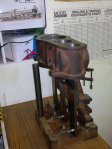
But, now we made a second trial assembly of the principal engine castings, to get a feel for how we were progressing – the engine is really growing now, and I can just lift it, but could not go far – I would guess it at about 80-100lbs.. and there is no crank, auxiliaries or valve gear yet!

Chrismas eve 2011

Well, we have reached a bit of a milestone I think – I have managed to erect the main castings (cylinder block, rear columns, base).

In the end I changed the order described in the manual, and mounted the rear columns first. Fitted the lower cylinder covers to the block (to ensure accurate positioning of the bolts, and then mounted the lower covers on the rear columns with a single bolt (as suggested) then remounted the block, spotting through the other mounting holes on to the column tops.

I came to this approach for two reasons:

1 -I did not manage the  machining the “spare bits” off the HP & LP covers accurately enough so there was about a 15thou gap between them. This meant that their angular position in the bores was not “totally” fixed.

2 – when I ran I trial erection, I discovered that very small lateral changes in the location of the block (displacing it along the line of the crank) produced very significant angular displacements of the covers – I am sure the geometry would  show this to be the case. So I concluded that it was better to settle the position of the covers (and their bolt holes) and manage the final alignment of the crank/slideways/cylinders  by control of the crank end-float.

Time will tell if I am right!

Next step is the front columns (a Boxing day job)! I am looking forward to this, although I have considerable concerns that the off-set turning jig to produce the offset footings will not result in a column that correctly matches the base and cylinder bolt holes without considerable “fettling”!

Drawing Errors

I tripped over a couple of problems –

1 – LP steamchest cover mounting bolts. It may be that my Technical Drawing A-level from the ’70s was to a different standard but only 8 of the 12 holes for the valve chest cover mounting holes should be drilled through. The 8 down each side do carry through to the block, but the 4 at the top and the bottom, should be blind – as the “clash” with the port pockets.

2 – The bottom (and top) cover mounting bolts. The location of these is not well defined on the drawings,  and care needs to be taken to ensure that they miss the ports in the cylinders (I wound up needing to redrill two on the LP side, as it became clear this was to be a problem.

3 – The bottom cylinder cover-to-column mounting holes. Again the location of these are not well defined on the drawings, and in the end  I wound up re-drilling these to ensure their correct location.

A Whole New Section on Drawing errors…

I have added a section to this site to log all the drawing errors I and others have noted… You are welcome to contribute too! Please see here.

A trial erection

So we reach the point where we can see if it looks like it will fit together. The engine is makes a lot of use of jigs, something new to me, but you can see how they work.

So firstly the front columns are clamped to an assembly jig located in the main bearing slots. Then a jig to locate the lower covers of the cylinders is clamped to the slideways,  then the whole cylinder block is lowered onto these covers – and you start to get a feel for how it’s going to look! and how heavy it is!

first erection - LP valve end
first erection – LP valve end

from the rearfrom the rear… and from the HP endfrom the HP end

The Castings Arrive!

Castings for Befur's Engines

Beauty in Cast Iron!

The engine ceases being and “idea” and transforms into a few hundred pounds of cast iron!

As planned, Louise and I returned from the sailing course and hot-footed it to Paris to meet up with Bruno Martin-Neuville and his friends from the Amateurs de Bateaux á Vapeur ( The French version of the SBA) and purchase this beautiful set of castings.

Bruno, Jean-Yves, and John entertained us wonderfully with a tour of their fabulous facilities in Severes on the outskirts of Paris and a very nice lunch. (we forgot to take pictures! but saw Midship, Melusine and others…)

So the winter’s work is now clear – to commence transforming these castings into a working engine – it’s clear that there are some “deamons” lurking in the drawings, so I am pleased to have the help and advice of some of the professionals from my Model Engineering club and the support of previous builders in the SBA